
The schematic forms the building block of every electrical circuit, and even if you aren’t designing one yourself, knowing how to read one is invaluable. And with some schematic reading knowledge in hand, you’ll be able to design, build, and ultimately troubleshoot your way through your design logic before heading on to your PCB layout.
But how in the world do you go about reading a schematic if it’s your first time? There’s a ton of symbols that might be new to you, all those random lines connecting everything together. Fear not, we’ve got you covered with a surefire way to read your first schematic in Autodesk Fusion 360 like a pro, in only 3 steps.
Step 1 – Your Building Blocks
Let’s start by going over all the symbols you might find on a typical schematic. While we won’t be covering every possible symbol, knowing the ones outlined below will make you dangerous enough to understand a typical schematic. And for anything you don’t know, remember to refer to a part’s datasheet. Here we go!
Resistors
Resistors are one of the most common building blocks you’ll find in an electrical circuit. Without these guys, those energy-efficient LEDs that we’ve come to depend on would never work! The resistor symbol will look different based on if you’re using the US or international standards. For the US, you’ll find a zigzag line connected with two terminals. The international symbol is just a plain rectangle with the same terminal connectors.

The resistor symbol in both US and International versions.
You’ll also want to be on the lookout for variable resistors and potentiometers. You can quickly identify these by looking for a diagonal arrow placed across the zigzag line for a variable resistor, and a horizontal arrow pointing towards the zigzag line for a potentiometer.
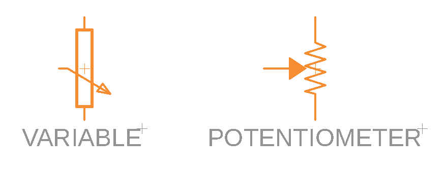
With the help of some new arrows, we can easily identify a variable resistor and potentiometer.
Capacitors
Capacitors are those lovely little components that can hold some serious charge. You’ll find two kinds of capacitors, polarized and nonpolarized, each of which will have two terminals connected.

Capacitors are easy enough to identify, with the polarized capacitor getting a curve for its cathode.
Inductors
Next up is the inductor. These guys are responsible for storing energy in the form of a magnetic field, all thanks to a simple coiled wire! Inductors are pretty easy to identify on a schematic, with the typical looping lines shown in US standards. International inductors are boxier, and you’ll want to look for a solid rectangle.
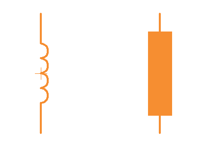
US inductors are easier to identify with their single looping coils.
Switches
These robust little switches are responsible for throwing your circuit into action. When open, no electricity flows, but in their closed state, the magic starts to happen. There are quite a few different forms of switches, but the simplest of the bunch is the single-pole/single-throw (SPST) switch that has two terminals and a half-connected line. This half-connected line represents whether your switch is in an open or closed state.

Power Sources
If you’re working with digital electronics, then you’ll likely only be dealing with DC voltage. But it’s also good to know what AC looks like should you ever stumble upon it on a schematic.
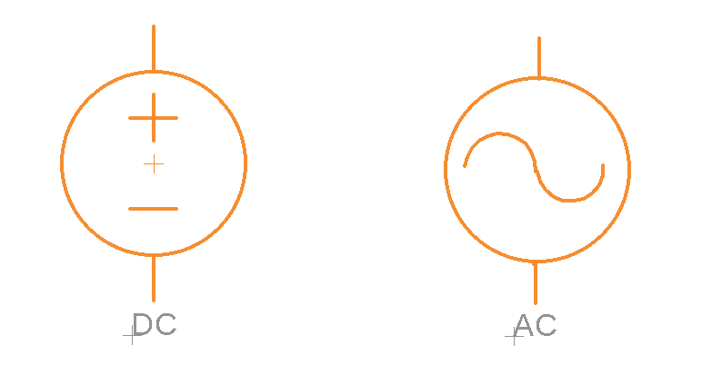
Your standard DC and AC voltage symbols for a schematic.
If your gadget is going to be powered by a battery, then your symbol will look entirely different. The battery symbol contains several lines, the top being the positive terminal and the bottom (and shorter) line being the negative terminal. And if your battery has more than one cell, expect to see multiple lines.
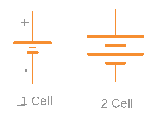
The common single-celled and two-celled battery symbol you’ll find on a schematic.
On more complex schematics, you’ll likely see symbols to indicate node voltages. These nodes are used to connect devices to a single terminal and will be designated as either 5V, 3.3V, VCC (which is the positive supply voltage of a power pin), and Ground (GND). You’ll notice in the image below that all of the positive node voltages are shown with an up arrow or triangle, and every ground voltage is either an arrow, set of lines or triangle all pointing downwards.

All the variations you need to know for your positive and ground voltages.
Diodes
Diodes have many functions, the most common being the fabled LED. There’s also the photodiode, which can create energy from light by acting as a mini solar cell. You’ll find the standard diode symbol by looking for a triangle resting against a vertical line with two connecting terminals on each end.

The standard diode symbol, not to be mistaken by a LED.
You can build off of this basic diode symbol to create LEDs and photodiodes by looking for a set of arrows. The arrows pointing away turn a diode into a LED, and arrows pointing toward the diode indicate a photodiode.
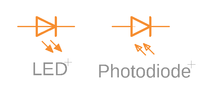
With the addition of some directional arrows, we’ve created a LED and photodiode.
Transistors
You’ve probably heard about transistors large and small. They’re the granddaddy of the electrical symbols and are responsible for powering all of the modern complexity in your computer. And if these bad boys didn’t exist, then you would never be reading this blog on your computer!
Transistors exist in two primary forms, as Bipolar Junction Transistors (BJTs) or Metal Oxide Field-Effect Transistors (MOSFETs).
You have two kinds of BJTs to look out for, both of which have three terminals for a collector, emitter, and base. You’ll notice in the image below that the emitter and collector pins are always in line with each other, with an arrow next to the emitter. The direction of this arrow determines whether the BJT is an NPN (Negative, Positive, Negative) or PNP (Positive, Negative, Positive) transistor.
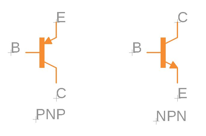
The two BJT transistors to be on the lookout for – NPN or PNP.
MOSFET transistors also have three terminals, but they’re called source, drain, and gate. You’ll find two different versions, an N-Channel and a P-Channel. The arrow located in the middle of each symbol below determines what kind of MOSFET transistor it is. An arrow pointing inward is an N-Channel MOSFET, and pointing out is a P-channel MOSFET.
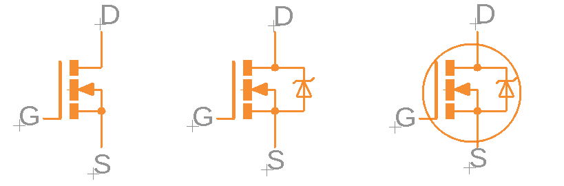
N-Channel MOSFETs.
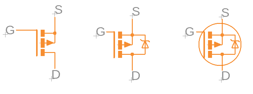
P-Channel MOSFETs
Logic Gates
Logic gates power our digital, binary world of 1s and 0s. The standard logic gates consist of AND, OR, NOT, and XOR, each with its unique symbol.
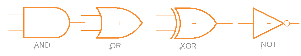
The building blocks of today’s binary logic gates.
If you go and add a circle to a logic gate, this creates an inverse effect of the gate’s value. For example, adding a circle to the AND, OR, or XNOR logic gates make them NAND, NOR, and XNO.
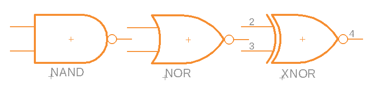
The addition of a simple circle (on the right) turns these into NAND, NOR, and XNOR gates.
Integrated Circuits
Integrated Circuits, or ICs, are the behemoths of the electrical symbol world. These guys don’t have a symbol, since they do so darn much, but you can easily recognize them when you see a giant rectangular box with a bunch of labeled pins inside.
Each pin will be given a name that will tell what function it serves, along with a number to identify a pin connection. You’ll also notice that each IC has a unique name, and this is super important since each IC has the same shape.
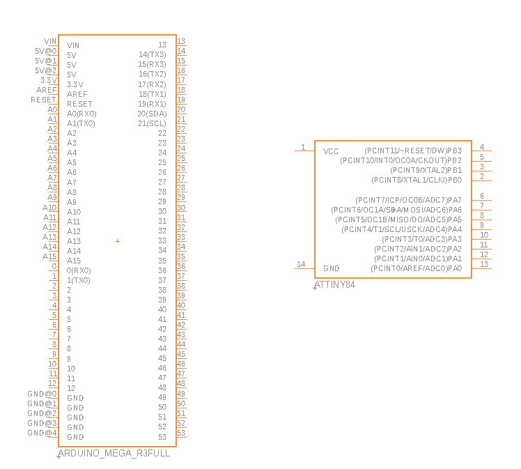
Here’s two unique Integrated Circuits, all with a variety of pins and functionality.
There are a few ICs that have unique symbols, including the operational amplifier (op-amp) and voltage regulator. You’ll notice in the image below that the op-amp has five terminals, whereas voltage regulars only require three terminals for input, output, and ground.
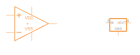
Five pins for the classic operational amplifier and three pins for the voltage regulator.
Crystals and Resonators
You’ll find these precious crystals powering the most important parts of a microcontroller – the clock signal. These little components have two terminals, whereas a resonator will have three terminals and two capacitors added into the mix.
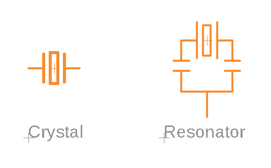
Here’s the crystal, and the bigger version, the resonator, with two capacitors added.
Headers and Connectors
If you’ve ever dug into the insides of your computer, then you’ll be very familiar with headers and connectors. These come in a variety of symbols depending on their function, and you’ll find them responsible for providing power, distributing data and bits, or serving as connection points.
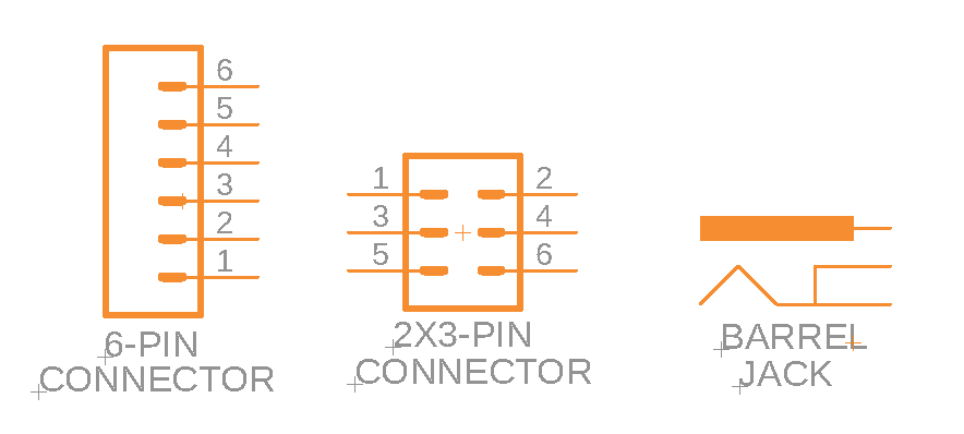
A small sampling of the available connectors you’ll find on a Fusion 360 schematic.
Transformers and Relays
You might have heard about those monolithic transformers that help to convert AC electricity into usable DC electricity in our homes. On a smaller scale, these devices are responsible for transferring power between two or more circuits, and you can identify the transformer by its dual coils.
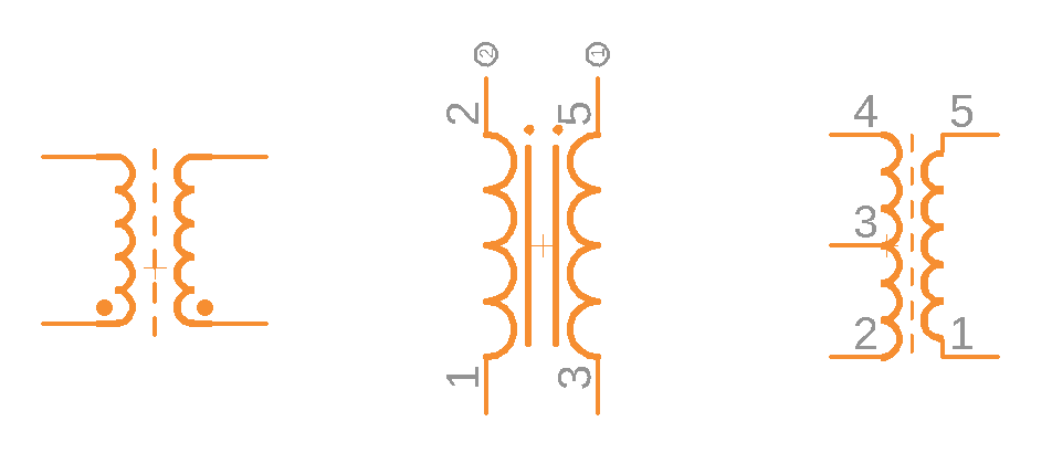
Several variations of a transformer, each with its set of coils.
Relays will use the coil found in the transformer symbol and add an electromagnet to switch a circuit’s power on/off.
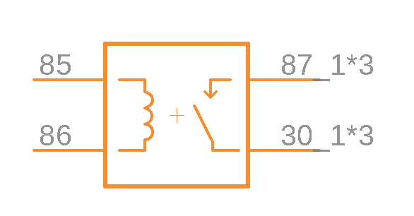
This is a relay symbol, adding an open switch to the transformer coil.
Speakers, Buzzers, and Motors
Turn up the sounds with some speakers, and buzzers! These simple devices look almost as they do in physical form and contain a positive and negative terminal.
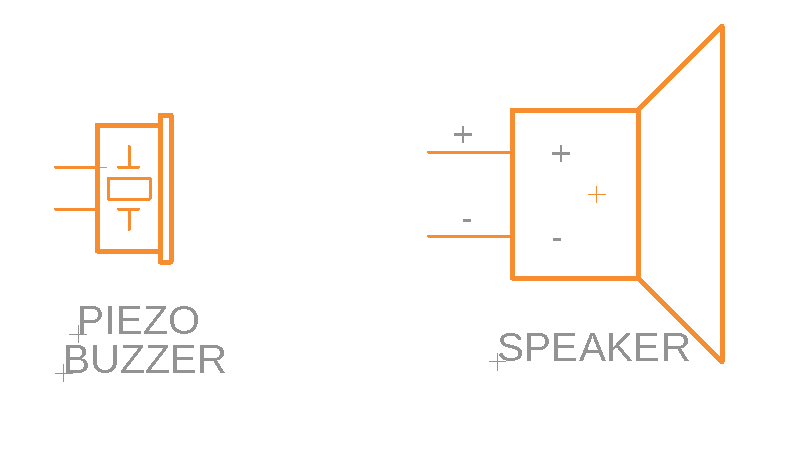
The speaker and buzzer are easy to identify with their almost lifelike shapes.
Motors make the world go round, and you can quickly identify these on a schematic by looking for a large M surrounded by a circle and a positive/negative terminal.
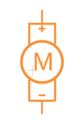
When in doubt, look for the giant M to identify a motor symbol.
Fuses and PTCs
If you’ve ever had the power blow out in your house, then you know what fuses are all about! These guys help to limit any massive influx of current that can cause fatal damage to your sensitive electronic devices. The line connecting the two terminals of a fuse looks similar to a physical fuse, and this is where the connection point will separate when too much current flows through the fuse.
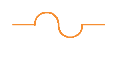
The simple fuse, brave protector of all our electronic devices.
A PTC, or positive temperature coefficient resistor, will vary in resistance based on its temperature. As the temperature increases, so do the resistance of a PTC, and vice versa.
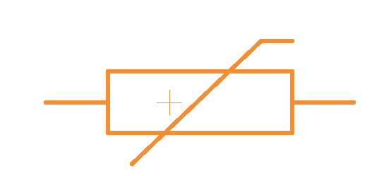
It’s getting hot in here! The resistance of this PTC increases with temperature.
That’s Enough to Make You Dangerous
That’s the end of step 1, and you now know enough schematic symbols to be dangerous. While we couldn’t cover every symbol known to man here, these basic symbols should get you 90% of the way when reading any schematic. If you ever need a helping hand remembering what a schematic symbol represents, try printing out this handy schematic symbol reference chart.
Step 2 – Connecting It Up
Now that you have a good understanding of all the basic building blocks of your schematic, the symbols, it’s time to understand how everything gets connected. There are two main elements to this step, connection points, and symbol identification.
Connect the Nets
All of those lines that you see on a schematic connecting your symbols are called nets. These nets will tell you exactly how components need to be wired together on your breadboard or PCB layout. Here’s a simple circuit below that shows the nets in a different color from the schematic symbols:
Nets come together to connect all of your schematic symbols.
Simple enough, right? Things can get a little complicated, though, when you start to build some complexity into your schematic. If you happen to see a wire splitting into multiple directions, it can mean one of two things:
It’s a node
There’s a node, or solid circle, in the middle of a pair of intersecting wires, then this is a junction. This means that the wires are electrically connected, and the current will be heading in both directions.
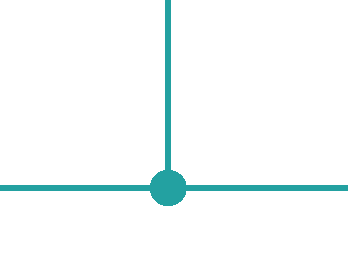
Be on the lookout for a node to identify net connection points.
It’s an overlap
If you don’t’ see any node in the middle of two intersecting wires, then you’ve got two separate wires that don’t share any electrical connection. And while we recommend avoiding this kind of overlap to avoid confusion, sometimes it just can’t be helped.

You might also run across some nets on your schematic, specifically near integrated circuits, that end in a label without actually being connected to anything. These net names are used to reduce wiring clutter on your schematic, but it’s assumed that their label connects them.
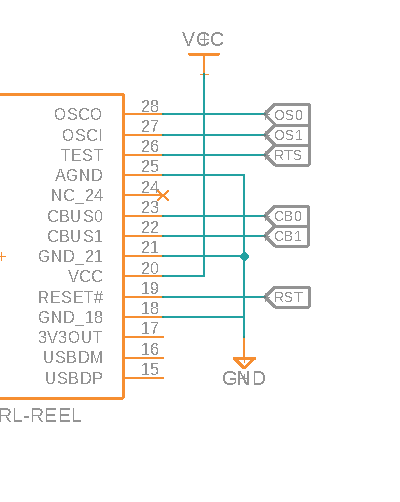
The nets on this integrated circuit end abruptly, but are still connected to the other label.
Give It a Name
Now that you understand how all of those symbols are connected with nets, let’s talk about all of the strange names that you’ve seen next to each symbol on a schematic. There are two parts to this, the Name and Value.
Names
Every symbol on a schematic is given a name and number. This helps to provide a unique identifier for each symbol, especially when you have multiple components of the same type being used. Symbol names will typically be a combination of a letter and a number, with the letter identifying the type of part, and the number being the unique variation of that symbol. These letter-number combination can sometimes be called a Reference Designator.
For example, a resistor will be labeled with an R. If you have multiple resistors to place, then they will follow a logical numbering sequence of R1, R2, R3, etc. Some other component letters to be aware of include:
- C – Capacitors
- D – Diodes
- L – Inductors
- Q – Transistors
- S – Switches
- U – Integrated Circuits
- Y – Crystals and Oscillators
Values
Values listed next to a symbol will help to identify how many ohms, farads, or henries a particular component has. Other symbols might use the value field to specify the name of an integrated circuit or the oscillating frequency of a crystal. Regardless of which value is listed, know that it’s the primary value you need to know for a part and is displayed for a reason.
Check out this example putting both the Name and Value concept together. As you can see in this circuit, we’ve got a resistor, labeled R4, which means it’s the fourth resistor in our schematic. And 1k Ohms is its value.
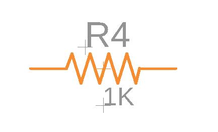
Every symbol on your schematic needs a name and value, just like this resistor.
Step 3 – Putting It All Together
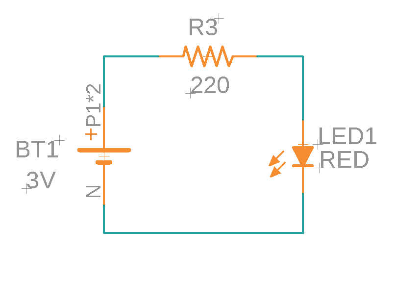
We’re now at the final step of our schematic reading lesson, the actual reading part! You can think of reading a schematic kind of like reading a book. You’ll always read from left to right, top to bottom. And every circuit will flow from input to output (or power to ground). In the example below, we have a super simple circuit for a LED flashlight. While your schematic will probably have way more stuff, this will give you a decent idea of how things flow together.

By following this circuit like a book, we start the left at our power source, which happens to be a battery. Moving with the flow of power, we then hit an open switch. When the switch closes, electricity will keep flowing through to catch a resistor, which then will make the LED light up without burning out!
You Are Now Schematic Literate
So there you have it, everything you need to know to read your first schematic in Autodesk Fusion 360 like a pro! If you want to see all of this in practice, be sure to check out this excellent video by Ben Heck on the Principles of Schematics. One final thing to keep in mind, as you begin to design your schematics, remember that another engineer will likely see it and interpret it later, whether that’s for a design review or to build another project. Do yourself and your fellow engineer a favor by making sure that all of your symbols are appropriately labeled, and even break things down into logical functional blocks to make it all easy to read.
Well, that is it for now. Ready to get started on making your first schematic? Try Fusion 360 for free today!


